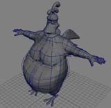
 Before I even started modelling, I tried to work out how I would do the animation setup for this guy. Since the beak is going to be made of a totally different material than the head, I decided to model it as a separate piece. Then I broke the beak down into upper and lower sections. I decided to make the head separate from the body, so I could model the head using nurbs and the body using subdivision surfaces.
I added a ruffle to the neck to make the head part separate from the body. By making the head out of a nurb sphere, I knew blend shapes would be a breeze to use for facial animation. Also, I could bind the base hierarchy of the sub-D surface to a skeleton fairly easily, so using them for the body was a no-brainer. The feet and tail are each modeled as individual pieces. They are different enough from the main body that it made sense to attach them to the body afterwards.
Intro
When I model, it helps me to have a sketch of a side view and a front view. The sketches don’t have to be to detailed, but they give me a starting point for modeling. Once I get the sketches done, I scan them and bring them into Photoshop. I clean up the images a little and try to scale them so they are the same size. One thing that helps me is to make one image and then paste both of the views in it. Then I take the line tool and run a series of black lines across both views. Make the lines big enough to see clearly but not cover up any details. After flattening the image, cut and paste the two views into different files, one for the front and one for the side. We are going to use these images as image planes that act as a template in Maya.
Once in Maya, load up the images as image planes. Image planes are a pain to use sometimes, so I have a melscript button that I use to turn them off and on. The easiest way to make one is to open up the attribute editor for the images plane and turn the display mode off and on. Then open up the script editor and select the text for each mode and drag it up to the tool shelf. Here’s an example of what the text should look like:
SetAttr imagePlane1.displayMode 2; //this turns the image plane on
SetAttr imagePlane1.displayMode 0; //this turns the image plane off
This make it easy to switch the image planes on and off.
Step 1: Chicken Head
Start with a nurbs sphere primitive and move/scale it into position for the skull.
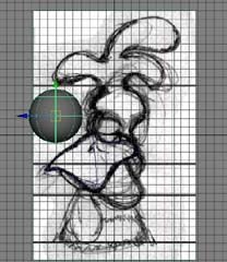
Nurbs sphere primitive for head
Split the sphere across the X-axis and delete one of the halves. We are only going to work on one side at a time. This will make it easier to add the detail and keep it symmetric across both sides. Either by using Artisan or lattices, mold the general form of the skull. Insert isoparms in areas that need details, specifically around the eyelids.
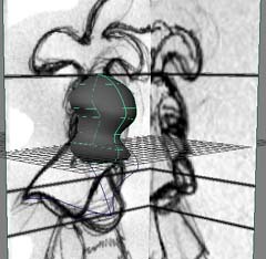
Rough shape of skull-notice the black lines on the image planes
This is pretty much the finished head. There is enough detail for the eyelids to blink and have the bags under they eyes move when the beak is added. I might need to change some things when I start to make blend shapes for the facial animation, but for now it will do. One trick is to go ahead and make a couple of spheres for the eyes and place them in the skull. This will give a starting point to make the sockets and eyelids.
Step 2: Creating the comb
Make a layer for the skull. Assign the skull and make the layer non-visible. Make the right side image plane visible and create a nurbs sphere. Manipulate the sphere by adding spans (or isoparms) untill you get the shape you want. Detach at the end and along the middle. Remember we are going to work on one side then mirror it.
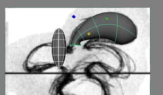
Manipulating a Nurbs sphere primitive
Copy this sphere for the other parts of the comb. I used lattices on them to get the shapes I was after. In all, I ended up with four pieces: the three rounded top parts and a base part that I made from detaching both ends off of a sphere. I guess I could have just used a cylinder, as the end result is the same.
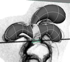
Four parts of the comb, all starting from spheres
Make a loft from the ends of the front and back combs pieces. Then manipulate the CVs to make the middle piece tangent to the others. Just remember that for a CV to be tangent it has to be in a direct line with two other CV’s. I find it easier to do this by looking in the front, top, and side views. I just try to visually guess and get it as close as I can. Do this for all four of the pieces edged. You can always use global stitch if you need to get the edges’ tangent. After assigning the pieces to their own layer leave the comb alone at this point and start working on the beak.
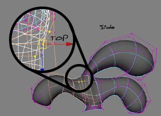
Tangency by hand
Step 3: The Beak
I ended up making the beak out of a sphere that I divided in half. Yeah, I know I’m getting a lot of mileage out of the sphere thing, but it’s an easy way to start. I promise I’ll do something different when we get to the body.
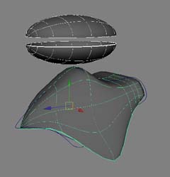
Before and after shots of the spheres
Sometimes when you want a complex shape, it’s easy to start out with curves formed in the rough shape that you want. The curves will give you a starting point in 3D. Also, if you’re sick of starting out with spheres, you can use the other modeling tools to form the needed shapes. Make an outline of curves to give you a nice form for the beak. You don’t have to do this but I find that it sometimes helps with complex shapes.
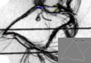
Beak curves in three dimensions
Now that we have a rough outline in 3D for the beak, take a sphere and rotate it so the ends are out to the side and the spans are lined up horizontally. Divide it up and hide the lower portion. By pushing and pulling CVs mould the sphere so that it fits within the curved framework that you created. I found that the CVs at the end of the sphere were pinching, I ended up straightening them out so that I no longer had a sphere. I did this so that when I mirrored and attached the two halves together I would get a clean blend between the two sides. Use lattices to further reshape the beak and delete the history on the beak when you are done.

CVs that form the end of beak
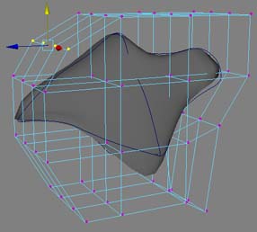
The old lattice trick
Duplicate the beak and scale the new one slightly so that it fits within the old one. Make sure that the edge that you are going to mirror across lies along the axis. Do this by selecting the inside hull and move it using the snap-to-grid option so that it is alligned with the axis. Using the EP Curve Tool, snap a curve to the end point (using snap-to-point or snap-to-curve) of each of the two beak sections. Bow out the curve by selecting the inside VCs and scale/move them out and down to make a nice shaped curve. Be sure not to move the curve endpoints from where they were snapped to the ends of the beak. Select the curve, then select the outside isoparms of the beak pieces. Use the Birail 1 tool and make a surface that goes between the two beak pieces. Attach the birail surface to the original beak piece and then attach the second beak piece to this one.
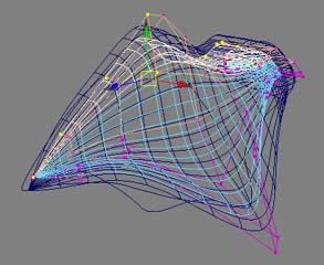
Select the inside hull and snap it to the axis
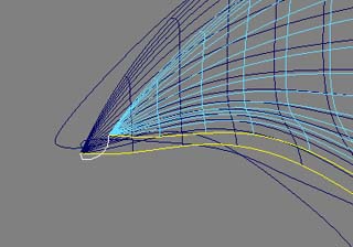
Birail surface with curve at front of beak
Repeat these steps for the lower beak. Remember to delete the history on the beak pieces when you are done. Also, create a layer for them and assign them to the layer. Name the pieces then hide the layer. At this point, duplicate all the geometry of the head, comb, and beak in the negative X and use the Instance option. This will give you an idea of how the whole thing will look. We’ll start on the body next.
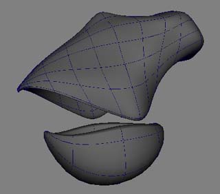
slots Arial”>Finished upper and lower beak pieces
Step 4: Onto the body
I said earlier that when we got to the body I’d start out differently. I decided to use sub-division surfaces for modeling it. Sub-division modeling is sometimes called volume modeling and it can be compared to sculpting a physical object. You start by defining the volume and then adding surface detail. The Eskimos had a way of sculpting by starting with a chunk of ivory and carving away everything that wasn’t a walrus. We’re going to do the same thing basically. We’ll start with a poly cube and divide it up until we get a fat chicken. Create a polygon cube and scale to roughly fit the body dimensions. Give it enough divisions so that you can sculpt it.
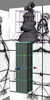
Poly block for a body
Pull the vertices to get a rough outline of the body. Try to think about where you will need pokie games online to play for detail. I like to keep the shape as a polygon object for as long as possible before I convert it into a sub-division object. One thing I do is to periodically convert it into a sub-D object to see how it is going to look then Undo the conversion so that I still have the original polygon. I have found Maya to be a little buggy when changing between the two different type of sub-Ds, so I try to keep it as a polygon until I start adding the surface detail. Try to keep the poly count as light as possible in these beginning steps.
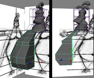
Shaping the volume of the body
To make an arm, first define a shoulder region out of the poly’s on the side of the body. What we are going to do next is to make a one large poly face to extrude out to the side for the arm out of a group of smaller poly faces. Select the four edges of the adjoining polygon’s and delete them. Select the resulting face and extrude it out a couple of times to make the rough shape of the arm.
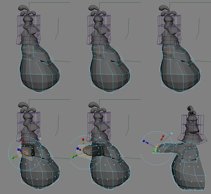
Pulling the arm out of body
Because we are basically dealing with polys its much easier to add things like arms, hands, and fingers, and still keep the body seamless. Add detail to the arm by using the split polygon tool to get the desired shape. Now might be a good time to use the convert to sub-d, then the undo trick to see how the shape is coming along. You might need to run the cleanup command under the polygon menu before you can covert to sub-Ds.
Next we are going to add the hand. I’m going to cheat and bring in a poly hand I already had modeled. I’m not going to go into detail on how to model a hand, there are plenty of tutorials that cover that on web. I imported the poly hand (it belonged to a low poly version of the rabbit, btw) and moved/scaled it into position at the end of the arm. One thing to note about sub-D surfaces and polygons: When you convert a polygon into sub-D’s, depending on the number of edges, there is a tendency for the resulting surface to be “skinny”. Since the hand was based on the rabbit’s, the fingers were already thin compared to what I wanted for the chicken and when I go to convert the poly’s to sub-D’s the fingers would get even thinner. One trick I found to fix this is to select all the vertices on the hand and using the move tool with the normal option, move the vertices in the normal direction. This will result in a much fatter hand and the scale will be roughly the same.
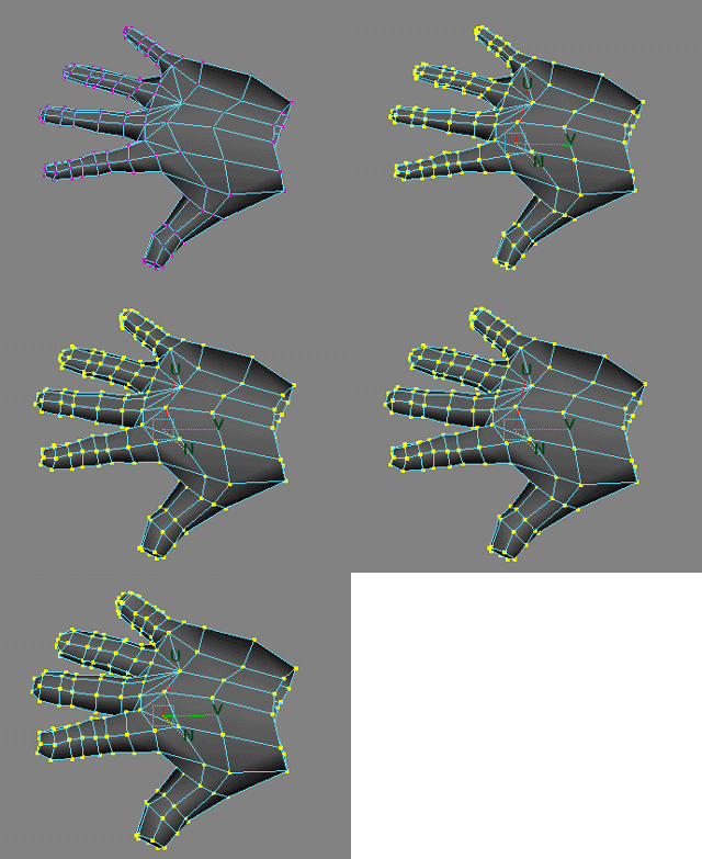
Fattening up
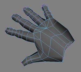
Resulting low poly hand
Now that we have got the hand roughly the shape and position that we want, connect it to the end of the arm using the poly combine command. Merge the vertices where the former poly shape hand joined the arm. This will give a seamless hand, arm, and body for one side.
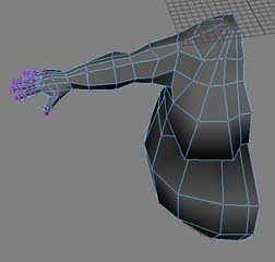
Seamless body half
Step 5: The foot
Since modeling the body was so easy using sub-Ds, I decided to use them for the feet as well. That way, if I wanted to join them to the body it would be relatively painless. I started by making the toes out of a curve that I revolved around the X-Axis. Then I converted the resulting nurbs surface to sub-Ds. I then extracted the vertices of the sub-D to get a polygon toe that I could use to make the rest of the foot. This might seem a little complicated, but I found it was easier to get the shape of the toe that I wanted. I duplicated the single polygon toe a couple of times to get the two additional front toes and then once more for the back “toe”. I moved/rotated each of the toes into place, then combined the front toes and merged the vertices.
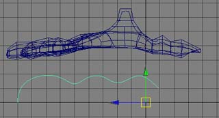
Toe outline curve compared to foot
I then deleted the edges of the inside faces and extruded that face a couple of times to meet the rear toe, just like I did for the shoulder and arm on the body. Depending on how you made the original toe you may need to append or add polygons to get that inside face. This formed the foot, which I then extruded the top of, to get the ankle. I sculpted the vertices on the end toe to get a claw. Convert the polygon foot into a sub-D surface.
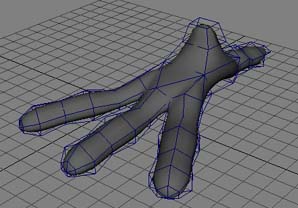
Sub-D foot
